     |
|
||
|
Users Browsing Forum
No Members and 1 Guests
|
| OT Circuit Board Design This thread currently has 576 views. |  |
|
|||||
 necro_nemesis necro_nemesis |
|
||||
 Hey Bucko, you're up. Complete MAACA-Wacko!  Posts
6,653
Gender
 Male MalePosts Per Day
3.49
Time Online
303 days 10 hours 42 minutes
Location
Newmarket, Ontario
Age
47
|
|
||||
|
|
||||
 websherpa websherpa |
|
||||
 Keep groovin' to 80's pinball machines! Complete MAACA-Wacko! Posts
3,344
Gender
MalePosts Per Day
2.17
Time Online
800 days 5 hours 48 minutes
Location
Waterdown, ON
Age
46
|
|
||||
|
|
||||
| necro_nemesis |
|
||||
Hey Bucko, you're up. Complete MAACA-Wacko! Posts
6,653
Gender
MalePosts Per Day
3.49
Time Online
303 days 10 hours 42 minutes
Location
Newmarket, Ontario
Age
47
|
|
||||
|
|
||||
| necro_nemesis |
|
||||
Hey Bucko, you're up. Complete MAACA-Wacko! Posts
6,653
Gender
MalePosts Per Day
3.49
Time Online
303 days 10 hours 42 minutes
Location
Newmarket, Ontario
Age
47
|
|
||||
|
|
||||
| necro_nemesis |
|
||||
Hey Bucko, you're up. Complete MAACA-Wacko! Posts
6,653
Gender
MalePosts Per Day
3.49
Time Online
303 days 10 hours 42 minutes
Location
Newmarket, Ontario
Age
47
|
|
||||
|
|
||||
| wbradley |
|
||||
Is it an atom? No, it's multiball! Complete MAACA-Wacko! Posts
2,181
Gender
MalePosts Per Day
4.03
Time Online
148 days 9 hours 30 minutes
Location
Thornhill, ON
Age
46
|
|
||||
|
|
||||
| Subpacket |
|
||||
 MAACA-Colonel  Posts
268
Gender
MalePosts Per Day
0.16
Time Online
10 days 20 minutes
Location
London, Ontario
|
|
||||
|
|
||||
| machine.slave |
|
||||
 I'LL TAKE YOUR HOUSE!! Complete MAACA-Wacko! Posts
3,264
Gender
MalePosts Per Day
2.13
Time Online
257 days 6 hours 12 minutes
Location
Brampton
Age
32
|
|
||||
|
|
||||
| necro_nemesis |
|
||||
Hey Bucko, you're up. Complete MAACA-Wacko! Posts
6,653
Gender
MalePosts Per Day
3.49
Time Online
303 days 10 hours 42 minutes
Location
Newmarket, Ontario
Age
47
|
|
||||
|
|
||||
| Tuborg |
|
||||
 Complete MAACA-Wacko! Posts
1,897
Posts Per Day
1.37
Time Online
476 days 18 hours 49 minutes
Location
Ottawa, ON, Canada
|
|
||||
|
|
||||
| necro_nemesis |
|
||||
Hey Bucko, you're up. Complete MAACA-Wacko! Posts
6,653
Gender
MalePosts Per Day
3.49
Time Online
303 days 10 hours 42 minutes
Location
Newmarket, Ontario
Age
47
|
|
||||
|
|
||||
| Tuborg |
|
||||
Complete MAACA-Wacko! Posts
1,897
Posts Per Day
1.37
Time Online
476 days 18 hours 49 minutes
Location
Ottawa, ON, Canada
|
|
||||
|
|
||||
|
|||||

 so I figured now would be a good time to play around with making a board. This board is pretty straight forward. Rectifies the voltage and gives a glowing effect without having to install numerous components.
 Logged

 I wanted to go two colour and more glow than flicker. Besides those things don't fit snugly into the holes provided.
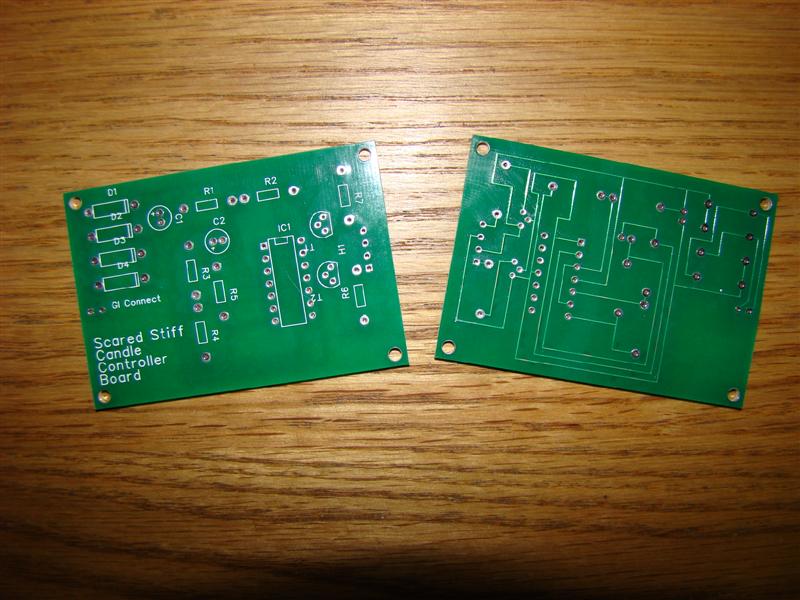


 , Wipe-Out, Pinball Pro: Challenger I, Swords of Fury, Stargate, Party Zone
| |
 MAACA ARCHIVES - JOIN THE NEW FORUM AT HTTP://WWW.MAACA.ORG › General Boards › MAACA Forum and Chat › OT Circuit Board Design MAACA ARCHIVES - JOIN THE NEW FORUM AT HTTP://WWW.MAACA.ORG › General Boards › MAACA Forum and Chat › OT Circuit Board Design |
| Thread Rating |
| There is currently no rating for this thread |


