Anyone on here work with CAM, Gerber files and circuit board production?
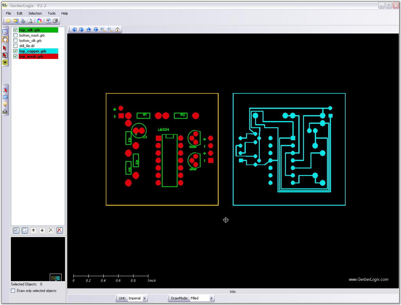
I was working with a program FreePCB and threw together this PCB just to get a handle on the software. Is this something that can be produced and are there any rules i.e. spacing of traces that I should be aware of in the design phase?
With it I can generate drill files and Gerber files for the traces, screening etc. This is the output as viewed with GerberLogix V2.2.
Anyone on here work with CAM, Gerber files and circuit board production?
I was working with a program FreePCB and threw together this PCB just to get a handle on the software. Is this something that can be produced and are there any rules i.e. spacing of traces that I should be aware of in the design phase?
With it I can generate drill files and Gerber files for the traces, screening etc. This is the output as viewed with GerberLogix V2.2.
When you think about it, if you're going to etch your own boards, there really are no hard and fast rules, but you do a test board and see if it flies. Remember that certain circuits run their traces very closely together.
Generally speaking however, I would say that if it is a high current circuit, then the traces need to be wider and spaced further, but for typical IC circuits, they can be quite thin and compact (although again it depends on the etching process whether your results will be good).
Now, all that being said, why don't you ask a circuit board producer, they take designs such as this and small run produce them for you and there are many such firms and certain they would be willing to give some advice on the prospect of gaining a client.
I found I can get 100 of these produced for $90. Two layer if required, silk screened and drilled. Don't know what I would do with a 100 of these but in the interest of figuring it out it might be worth going through the process. I went through the trouble of routing it single layer in case I wanted to try etching one myself. It's a good little puzzle to attempt limiting the layers and get the traces where they need to go then varifying the circuit.
My sense in looking at it is that trying to etch my own I may have some issues getting those narrow traces down clean. Anyone have experience with etching their own boards and if so is this going to be a problem? The whole board is a little over an inch square to give an idea of scale.
In my younger age, I designed and manually etched a few boards, and had the following recommendations applied at the time:
- make sure each trace is wide enough to get around masking tolerances for etching (in addition to basic current capabilities); easy to have an 'open' trace if too narrow;
- make sure each trace is far enough from its neighbor to avoid potential short either due to improper etching in a spot, or due to clumsy soldering process/practices.
The newer technology of course has a lot less of these issues now, however I still would aim to leave more space between traces than what is shown in your pic (the three traces very close to one another).
Good luck ! - Sylvain.
Looking for 1966 Bally Capersville, 1967 Bally The Wiggler, 1981 Stern Viper, 1986 Pinstar Gamatron, 1986 Williams Grand Lizard, 1991 Williams Bride of Pinbot, and a few others. Cash or some trades available. Could also repair a machine of yours +/-$ if needed, in exchange for one machine on my want list, non-working/unshopped welcome!
Make your traces as thick as possible, leave more room between traces. For example, those 3 traces between the DIP IC pads, space them out and leave the same amount of gap between the traces and the adjacent pads on either side. Make power & ground traces as wide as you can... they pick up less resistance & noise that way. Bigger is always better when it comes to traces & pads, but you need to leave as much space as you can afford between them or else you can wind up with bridges upon etching.
Also, if you going to 'etch your own', make your pads as big as possible. Often hand-drilling will lift & remove small pads.
Works best with the paper listed from Staples. Your laser printer will have an effect as well on the outcome. The older the printer, the better. Newer ones (color ones) don't seem to lay down enough toner to transfer properly. It takes some practice to get it right.
Avoid those special "PCB Toner Transfer Sheets" (usually blue) you see on ebay... I found them to be worse than Staples photo paper by a long shot.
For echant, use Ferric Chloride, avoid the Blue crystally stuff (Ammonia Persulphate??, it's not strong enough. You need to warm it up a bit to make it etch faster (the faster it etchs, the less chance you will have of trace undercutting).
Once you get it nailed down, it's a breeze. Or, go with the specialized PCB manufactoring services if you can afford it, or need multiple copies. They typically require only a gerber & NC drill file, but they may be fussy on what program you use to create them, and may want the main pcb file so they can clean it up and properly adjust the apertures. They don't always deal with different vendor's CAD programs, sometimes only the commercial versions.
For getting small quantities of PCBs manufactured, I use this place: http://batchpcb.com
"You submit your PCB design, we add your design to the batch of orders. When the batch is big enough (usually about 1 week), the batch is set off for manufacture. 10 days later, the individual boards are received by us. We then split the orders up and mail your order to you."
I recently got a couple of 1"x1.5"adapter boards made there (which I designed in Eagle) and it cost me about $4.50/ea + $10 flat shipping. Much better than paying $90 or so to get 100 boards made, especially if you're just prototyping a design. The turnaround time is a little longer than a normal PCB fab house, since they wait for a full 'batch' before sending it out, but if you're not in a huge rush, it's a good option. I think I got my boards back in about 3 weeks.
Thanks for the input. That batch PCB site seems to be a good way to trial boards in low volume and I certainly don't mind the wait.
ToMMy on the drilling is there any merit in drilling first and etching afterward?
Not sure if I am going to go the etch your own board route. With all the mechanical and electronic crap lying around the workshop, if I add in the chemistry to do the boards I think I could be considered a certifiable mad scientist at that point. Too humid for the straight jacket this time of year.
ToMMy on the drilling is there any merit in drilling first and etching afterward?
No, it just gives the etchant more places to eat through your artwork mask. You can't protect the copper edges around the holes.
http://batchpcb.com sounds like a neat way to go .... saves turning half the stuff in your shop yellow with ferric chloride stains. My wife is still miffed at the color of her laundry tub now not to mention the top of the freezer which I'm no longer allowed to use as 2nd workbench
I wasn't happy with any of the candle solutions out there for SS. Pinball Pro sells an led encased in resin. GI voltage is AC and therefore you have to put in at the very least a full wave BR to just get them to light and remain on otherwise your going off an opto circuit possibly. Next to the skull pile going through it's animations it's hardly an effect to have two more leds just on. I got a hold of Terry Nelson to see if I could snag one of his boards. Basically he's gotten out of doing them. Terry's board has a nice effect but you can't get it.
My preference was to embed two leds per candle, one orange and one red. I didn't want them flashing, there is enough in that back corner flashing to give you a seizure with skull pile modded, so I elected to have them smoothly alternate in intensity like a glowing flame. This circuit does exact that and in fact I bread boarded the whole thing with a diode bridge and cap to smooth out ripple and hooked it to SS's 5 VAC GI string where it works like a charm.
So at the end of the day I wanted this effect and I don't plan on plastering a bread board to the back of my pf so I figured now would be a good time to play around with making a board. This board is pretty straight forward. Rectifies the voltage and gives a glowing effect without having to install numerous components.
Keep groovin' to 80's pinball machines! Complete MAACA-Wacko!
Posts
3,344
Gender
Male
Posts Per Day
2.17
Time Online
800 days 5 hours 48 minutes
Location
Waterdown, ON
Age
46
Of course your solution is perfect, but did you give thought to lo-teching it with any one of the numerous battery driven flickering led candle solutions out there? Or was that just not going to be "stiff" enough? I use them for halloween effects (much easier than re-lighting candles blown out by the wind...), my first thought would be to just tap into one of the 5 volt DC sources ... it's not like an LED circuit is going to draw enough juice to disrupt (if you take some precautions).
Yes, before any of this I did look at the $1 flickering candle solution and it was viable too.... with about the same amount of added board work. I wanted to go two colour and more glow than flicker. Besides those things don't fit snugly into the holes provided.
I would still require a supply voltage, my one of choice is the GI because when you get Scared Stiff the GI goes out and I want the candles off at that time. Optos are still getting power during the mode so using opto power it is not the effect I want. To me the solution is a board with a basic full wave rectifier. The GI runs at about 5.6 VAC. With a simple diode full wave bridge and small cap circuit loss is minimal and I am getting 4.7 VDC with low enough ripple that the LM324 operates.
Assembled. Unfortunately one of the two boards was lost in the name of science. The damn manufacturer of a transistor reversed the pinouts and caused me to go through some head scratching and board abuses to figure this out.
The purpose of going through the experiment was to learn the process. What I would modify should I do another circuit is marginally increase the drill diameters for ease of assembly, also rather than using transistor symbology I would mark E/B/C so as to allow for substitution for other manufacturers product given the issue I ran into. Not a whole lot of changes would be made but enough to prove to me the merits in prototyping something like this.
The project met it's aim in ensuring I could design, have produced and assemble a working board. I was thinking of doing the translite TZ door mod as a single board next. On that one I would like to have a driver board transistor trip an effect like AFM saucers mod does.
Own Magic, Star Gazer, Batman Forever, STTNG, Mystery Castle (project)
Gone Fairy, Secret Service, Meteor x3, Title Fight, Eight Ball Deluxe, Bone Busters Inc., Seawitch, Starship Troopers, Strange Science, Arena, Hook, Pin*Bot x2, Time Warp, Motordome, Robocop, Black hole, Jurassic Park , Wipe-Out, Pinball Pro: Challenger I, Swords of Fury, Stargate, Party Zone
OK - I'm jealous. How did you figure out the circuit - and why did you choose to use op amps? Just wanting to learn...
The credit goes to Bill Bowden for designing the fader circuit. I didn't get struck by lightning and suddenly arrive at this design. I simply made some adjustments to it and added a rectifier operate from the 5VAC GI circuit.
Here is the theory of operation.
In operation, a linear 3 volt (peak to peak) ramping waveform is generated at pin 1 of the LM1458 IC and buffered with an emitter follower transistor stage. The 22uF capacitor and 47K resistor connected to pin 2 establish the frequency which is about 0.5 Hz. You can make the rate adjustable by using a 100K potentiometer in place of the 47K resistor at pin 2.
The circuit consists of two operational amplifiers (opamps), one producing a slow rising and falling voltage from about 3 volts to 6 volts, and the other (on the right) is used as a voltage comparator, the output of which supplies a alternating voltage switching between 2 and 7 volts to charge and discharge the capacitor with a constant current.
Each of the op-amps has one of the inputs (pins 3 and 6) tied to a fixed voltage established by two 47K resistors so that the reference is half the supply voltage or 4.5 volts. The left opamp is connected as an inverting amplifier with a capacitor placed between the output (pin 1) and the inverting input (pin 2). The right opamp is connected as a voltage comparator so that the output on pin 7 will be low when the input is below the reference and high when the input is higher than the reference. A 100K resistor is connected between the comparator output and input to provide positive feedback and pulls the input above or below the switching point when the threshold is reached. When the comparator output changes at pin 7, the direction of the current changes through the capacitor which in turn causes the inverting opamp to move in the opposite direction. This yields a linear ramping waveform or triangle waveform at pin 1 of the inverting opamp. It is always moving slowly up or down, so that the voltage on the non-inverting input stays constant at 4.5 volts.
Adjustments to the point where the LEDs extinguish can be made by altering the resistor value at pin 3 and 6 to ground. I found a 56K in place of the 47k shown worked a little better with the particular LEDs used. You can experiment with this value to get the desired effect.
A PNP transistor was added to the circuit provide a reverse effect of a second colour illuminating when the first dims. I am still experimenting with various LEDs embedded in clear resin to provide the yellow/red glow I am looking for. Next attempt will be stacking two diffuse square ones in the back and see what effect that produces.
Thanks. In reality not much is invented these days in my opinion - just refining other ideas. It is hard to separate "invention" from "development". Love the look and congrats!
I finally had a chance to put in the candles I consider to be the final design and here is the outcome. I calibrated the rate of oscillation between the orange and red LEDs to be in sync with primary music track. The LEDs go out at the appropriate times in game play through being run through the GI 5VAC circuit. The blue lines running up the right side of the playfield are just an artifact of the skull pile LEDs and not visible to the eye.


 necro_nemesis

 Male
Male
 websherpa


 Logged


 not to mention the top of the freezer which I'm no longer allowed to use as 2nd workbench
  I wanted to go two colour and more glow than flicker. Besides those things don't fit snugly into the holes provided.
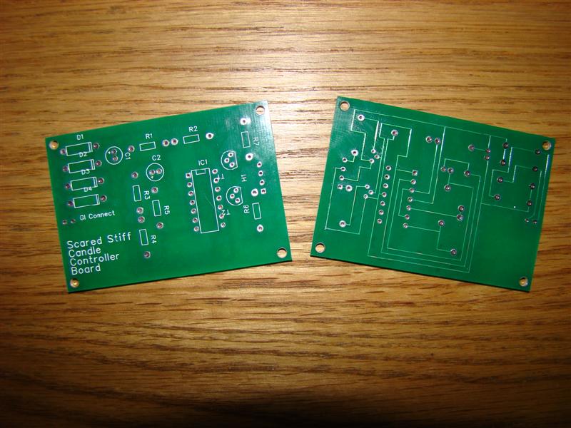


 , Wipe-Out, Pinball Pro: Challenger I, Swords of Fury, Stargate, Party Zone
 MAACA ARCHIVES - JOIN THE NEW FORUM AT HTTP://WWW.MAACA.ORG › General Boards › MAACA Forum and Chat › OT Circuit Board Design


